product features
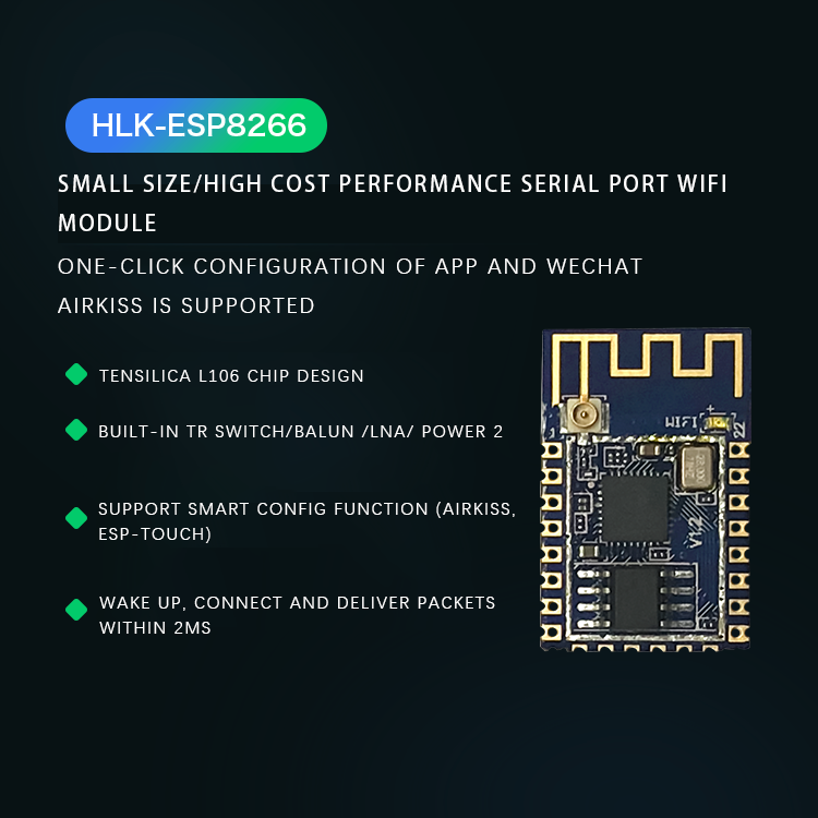
PRODUCT FEATURES
Support 802.11b/g/n protocol
Built-in Tensilica L106 ultra-low power consumption 32-bit micro MCU, main frequency supports 80 MHz and 160 MHz, supports RTOS
Built-in 10-bit high precision ADC
Built-in TCP/IP protocol stack
Built-in TR switch, balun, LNA, power amplifier and matching network
Built-in PLL, voltage regulator and power management components, +20 dBm output power in 802.11b mode
A-MPDU, A-MSDU aggregation and 0.4s guard interval
WiFi@2.4 GHz, support WPA/WPA2 security mode
Support STA/AP/STA+AP working mode
Support Smart Config function (airkiss, esp-touch)
Standby power consumption is less than 1.0mW
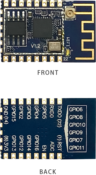
Product Image
PRODUCT PICTURES
Hardware description
HARDWARE DESCRIPTION
Pin description
| Numbering | Features | Description |
| 1 | RST | Description |
| 2 | ADC | A/D conversion result:
input voltage range 0~1V
value range 0~1024 |
| 3 | EN | Enable, high level work |
| 4 | GPIO16 | When connected to the RST pin, it can be waked up from deep sleep |
| 5 | GPIO14 | SPI_CLK |
| 6 | GPIO12 | SPI_MISO |
| 7 | GPIO13 | SPI_MOSI; UART0_CTS |
| 8 | VCC | Power 3.3V |
| 9 | CS0 | Chip Select |
| 10 | MISO | Slave output host input |
| 11 | GPIO9 | GPIO9 |
| 12 | GPIO10 | GPIO10 |
| 13 | MOSI | MOSI |
| 14 | SCLK | clock |
| 15 | GND | Public land |
| 16 | GPIO15 | MTDO; SPICS; UART0_RTS |
| 17 | GPIO2 | GPIO2; UART1_TXD |
| 18 | GPIO0 | GPIO0 |
| 19 | GPIO5 | GPIO5 |
| 20 | GPIO4 | GPIO4 |
| twenty one | RXD0 | UART0_RXD; GPIO3 |
| twenty two | TXD0 | UART0_TXD; GPIO1 |
Pin mode
| mode | GPIO level | GPIO0 level | GPIO2 level |
| UART download | 0 | 0 | 1 |
| Flash Boot | 0 | 1 | 1 |
Interface Description
| Interface name | Pin | Description |
| SPI interface | GPIO12(MISO), GPIO13 (MOSI), GPIO14(CLK), GPIO15(CS) | Can be connected with 4SPI Flash, display screen and MCU, etc. |
| PWM interface | GPIO12(R), GPIO15(G), GPIO13(B) | Can be used to control colored lights, buzzers, relays and motors, etc. |
| IR interface | GPIO14(IR_T), GPIO5(IR_R) | The IR Remote Control4 interface is implemented by software, the interface uses NEC encoding and modulation and demodulation, and 38KHz modulated carrier |
| I2C interface | GPIO14(SCL), GPIO2(SDA) | Connect sensor and display |
| UART interface | UART0: TXD (U0TXD), RXD (U0RXD), GPIO15 (RTS), GPIO1 3 (CTS) UART1: GPIO | An external device with UART interface can be connected. |
| I2S interface | I2S input: GPIO12(I2SI_ DATA); GPIO13(I2SI_BCK); GPIO14(I2SI _WS); | Mainly used for audio collection, processing and transmission. |
| I2S output: GPIO15(I2SO _BCK); GPIO3(I2SO_DAT A); GPIO2(I2SO_WS) |
|
Other interface description
Built-in MCU description
ESP8266EX has built-in Tensilica L106 ultra-low power consumption 32-bit micro MCU with 16-bit compact mode, main frequency supports 80MHz and 160 MHz, and RTOS. Currently, only 20% of MIPS is used in the WiFi protocol stack, and the rest can be used for application development. MCU can cooperate with other parts of the chip through the following interfaces:
1. The coded RAM/ROM interface (iBus) that connects to the storage controller and can also be used to access the external flash memory
2. Also connect to the data RAM interface of the storage controller (dBus)
3. AHB interface to access registers
Built-in SRAM and ROM
The ESP8266EX chip has a built-in storage controller, including ROM and SRAM. The MCU can access the memory controller through iBus, dBus and AHB interfaces. These interfaces can access ROM or RAM units, and the storage arbiter determines the running sequence in the order of arrival.
Based on the current use of SRAM in Espressif’s Demo SDK, the remaining SRAM space available to users is: RAM size < 36kB (In station mode, the heap+data area can be roughly 36KB after connecting to the router.) There is currently no programmable ROM on the ESP8266EX chip. , The user program is stored in SPI Flash.
SPI Flash
The current ESP8266EX chip supports external Flash using SPI interface, theoretically it can support up to 16 MB of SPI flash. At present, the external connection of this module is 4MB SPI Flash.
Recommended Flash capacity: 1 MB-16MB. Supported SPI modes: Support Standard SPI, Dual SPI, DIO SPI, QIO SPI, and Quad SPI.
Note that you need to select the corresponding mode in the download tool when downloading the firmware, otherwise the program will not run correctly after downloading.
Crystal oscillator
Currently crystals 40M, 26M and 24M are all supported. Please pay attention to selecting the corresponding crystal type in the download tool when using it. 4.5V~5.5V. The ground adjustment capacitors C1 and C2 added to the crystal oscillator input and output can not be set to fixed values. The value range is 6pF~22pF. The specific value needs to be adjusted and determined after system testing.
Based on the current mainstream crystal oscillators in the market, the capacitances C1 and C2 added to the input and output of a general 26Mhz crystal oscillator are within 10pF; the capacitances added to the input and output of a general 40MHz crystal oscillator are 10pF<C1, C2<22pF. The selected crystal oscillator must have an accuracy of ±10PPM. The operating temperature of the crystal oscillator is -20℃-85℃.
The position of the crystal oscillator should be as close as possible to the XTAL Pins of the chip (the trace should not be too long), and the trace of the crystal oscillator must be wrapped with ground for good shielding. Input and output wiring cannot be perforated, that is, they cannot cross layers. The input and output traces of the crystal oscillator cannot cross, nor can cross layers. Please place the bypass capacitors for the input and output of the crystal oscillator close to the left and right sides of the chip, and try not to put it on the niche.
Function Description
FUNCTION DESCRIPTION
Module functions can be divided into two modes: serial port to WiFi STA and serial port to WiFi AP.

·In this mode, the WAN and LAN functions are turned off. Through settings, the data of COM1 and WiFi can be converted mutually.
·WiFi CLIENT can be configured as a dynamic IP address (DHCP) or a static IP address (STATIC).
·WiFi security supports all current encryption methods.

·In this mode (AP mode), the WAN and LAN functions are closed, and the data of COM1 and WiFi can be converted mutually through setting.
·The WiFi device can connect to the product and become a device under the WiFi LAN.
·WiFi security supports all current encryption methods.
Serial port working status conversion
The module defines the working status of the serial port as two modes: transparent transmission mode and AT command mode. After normal power-on, the module automatically enters the AT command mode.
How to enter transparent transmission mode in AT command mode:
Send AT command: AT+CIPMODE=1 (enable transparent transmission mode)
·After enabling the transparent transmission mode, you need to send the AT+CIPSEND command to send the transparent data.
Steps to enter AT command mode in transparent transmission mode:
1. Exit sending data: In the process of transparently transmitting data, if a single packet of data "+++" is recognized, then the transparently transmitting will be exited.
·If you use the keyboard to type in "+++", it may take too long, and it is not considered as three consecutive "+". It is recommended to use a serial port to send "+++" at once, and Please be careful not to carry invisible characters such as spaces or line feeds.
·After that, please wait at least 1 second before sending the next AT command
2. Send AT command: AT+CIPMODE=0 (exit transparent transmission mode)
The serial port/network data conversion of the product is divided into 4 modes: TCP Server, TCP Clinet, UDP Server, UDP Client.
TCP Sercer

·In this mode, the module monitors the specified port and waits for the TCP Client to connect. After the connection is connected, all TCP data is sent directly to the serial port, and the data from the serial port is sent to all TCP Clients.
TCP Client

·In this mode, the module connects to the specified domain name/IP and port. All data sent from the TCP Server end is sent directly to the serial port, and data from the serial port is sent to the TCP Server end.
·The abnormal network will cause the product to reconnect actively. When TCP active reconnection is available, TCP Server will actively disconnect, and the product will actively reconnect immediately, otherwise the module will not reconnect.
UDP Server

·In this mode, the module opens the local designated port. Once the data sent to this port is received, the module will send the data to the serial port and record the remote IP and port. The module will only record the remote information of the last connection. The data received by the serial port will be sent directly to the recorded remote IP and port.
UDP Client

·In this mode, the module directly sends serial port data to the specified ip and port. The data returned from the server will be sent to the serial port.


 Official mall
 Taobao shop
 TMALL
TMALL