DC-DC 5W-24V-A Power module selection
MULTIPLE SPECIFICATIONS AVAILABLE
Utra-wide input voltage 9~36V iput/5v regulated output
| MODEL | POWER | VOTAGE | ELECTRICITY |
| HLK-5D2405A | 5W | 5V | 1000mA |
| HLK-5D2412A | 5W | 12V | 417mA |
| HLK-5D2415A | 5W | 15V | 333mA |
| HLK-5D2424A | 5W | 24V | 208mA |
| *The appearance and pin size of the same series of products are the same |
| *The appearance size of the product is 25.4x25.4x11mm |
product features
PRODUCT FEATURES
Ultra-thin small size standard package and standard pins
Wide range input (4:1) voltage: 9~36VDC
Low power consumption, environmental protection, standby power consumption is only 0.036W (typical value)
Input and output isolation withstand voltage 1500VDC
Super fast start: 1ms (typical value)
High efficiency, 90% conversion efficiency (Typ)
Operating temperature range: -40°C~+85°C
Good output short circuit and over current protection and self-recovery
High reliability, long life design, continuous work over 100000H
It is potted with high-quality environmentally friendly waterproof and thermal conductive glue, moisture-proof and vibration-proof, and meets the waterproof and dust-proof IP65 standard
Meet UL/CE/EMC and safety testing requirements
Can be used in medical, industrial control, electric power, instrumentation, communication, railway and other fields
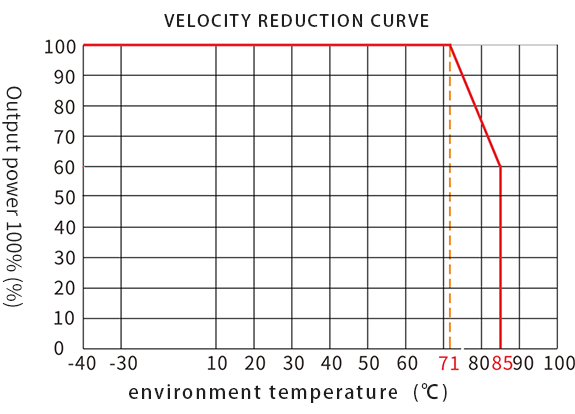
Operating temperature environment and load characteristics
WORKING ENVIRONMENT TEMPERATURE & LOAD CHARACTERISTICS
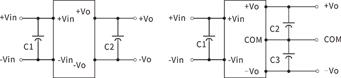
Typical application circuit
APPLICATION CIRCUIT
Recommended test circuit
Generally recommended capacitance: C1: 47-100μF; C2, C3: 10-22μF.
All DC/DC converters of this series are tested according to the recommended test circuit shown in the figure below before leaving the factory.
If it is required to further reduce the input and output ripple, the input and output external capacitors C1, C2, C3 can be increased or selected in series with capacitors with a small equivalent impedance, but the capacitance cannot be greater than the maximum capacitive load of the product.
EMC solution-recommended circuit
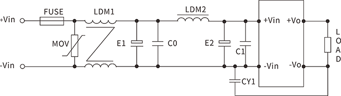
Recommended parameters:
FUSE: Connect the corresponding fuse according to customer needs
MOV varistor: 14D330K
LDM1/common mode inductance: 10mH
E1, E2 electrolytic capacitor: 100μF/50V
C0, C1 ceramic capacitors: 1μF/50V
LDM2 differential mode inductor: 10μH
CY1 safety Y2 capacitor: 1nF/250Vac
Output filter peripheral recommended circuit
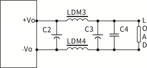
Note:
1. C2 and C3 use high frequency and low resistance electrolytic capacitors, and the total capacity should not exceed the maximum capacitive load marked in the manual, otherwise the module will not start normally.
2. For capacitive load, a minimum load of 3% must be guaranteed, otherwise it will cause abnormal output of the module.
Recommended parameters:
| Device code | 5V output | 9V/12V/15V output | 24V output |
| LDM3/4 inductance | 1μH | 2.2μH | 4.7μH |
| C2/3 electrolytic capacitor | 220μF | 100μF | 68μF |
| C4 ceramic capacitor | 1μF/50V |
Ripple & noise test: twisted pair method 20MHz bandwidth
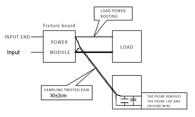
testing method:
1. Ripple noise is connected using 12# twisted pair, the oscilloscope bandwidth is set to 20MHz, 100M bandwidth probe, and 0.1uF polypropylene capacitor and 47uF high frequency low resistance electrolytic capacitor are connected in parallel to the probe end, and the oscilloscope sampling uses Sample sampling mode .
2. Connect the power input terminal to the input power supply, and the power output is connected to the electronic load through the fixture board. For testing, use a 30cm±2cm sampling line to sample directly from the power output port. The power line selects the corresponding wire diameter wire with insulation according to the output current. (As shown in FIG)
Dimensions
DIMENSIONS
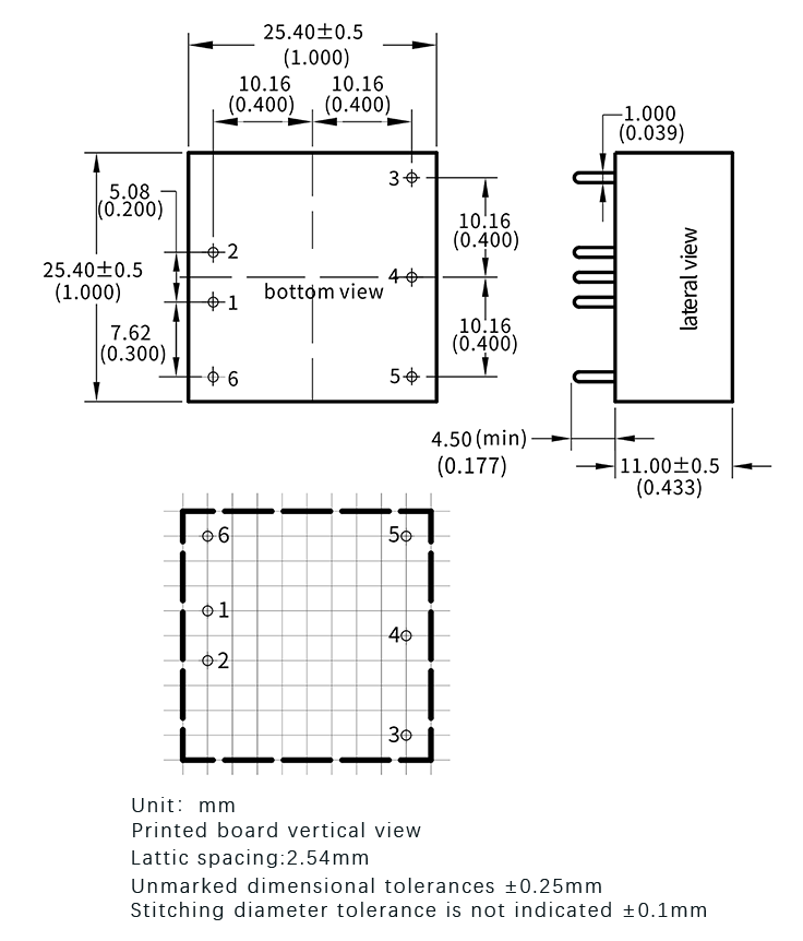
Pin description:
1: -Vin input negative; 2: +Vin input positive; 3: +Vo output positive; 4: NC; 5: -Vo output negative; 6: NC
*Note: If the definition of each pin of the power module does not match the selection manual, the label on the physical label shall prevail.


 Official mall
 Taobao shop
 TMALL
TMALL