A variety of specifications of power modules to choose
MULTIPLE SPECIFICATIONS AVAILABLE
1W constant pressure 24V(soil 10% Vin) input/isolated unregulated output
| MODEL | POWER | VOLTAGE | ELECTRICITY |
| HLK-1D2405 | 1W | 5V | 200mA |
| HLK-1D2412 | 1W | 12V | 84mA |
| HLK-1D2415 | 1W | 15V | 67mA |
| HLK-1D2424 | 1W | 24V | 42mA |
| *The same type of power module wind package size is consistent |
| *International standard pin size 11.5×10×6mm |
product features
PRODUCT FEATURES
Ultra-miniature standard package SIP package and standard pins
Constant voltage input, isolated unregulated single output, 1W
Input and output isolation withstand voltage 1500VDC
Low ripple/noise (20MH bandwidth) < 100mVp-p
High efficiency, conversion efficiency up to 80% (Typ)
Operating temperature range: -40°C~+85°C
High reliability, long life design, MTBF≥3500000H
Potting and sealing with high-quality environmentally friendly waterproof and thermal conductive glue, dustproof, moistureproof, shockproof and flame retardant
Meet UL/CE/EMC and safety testing requirements
Can be used in medical, industrial control, electric power, instrumentation, communication, railway and other fields
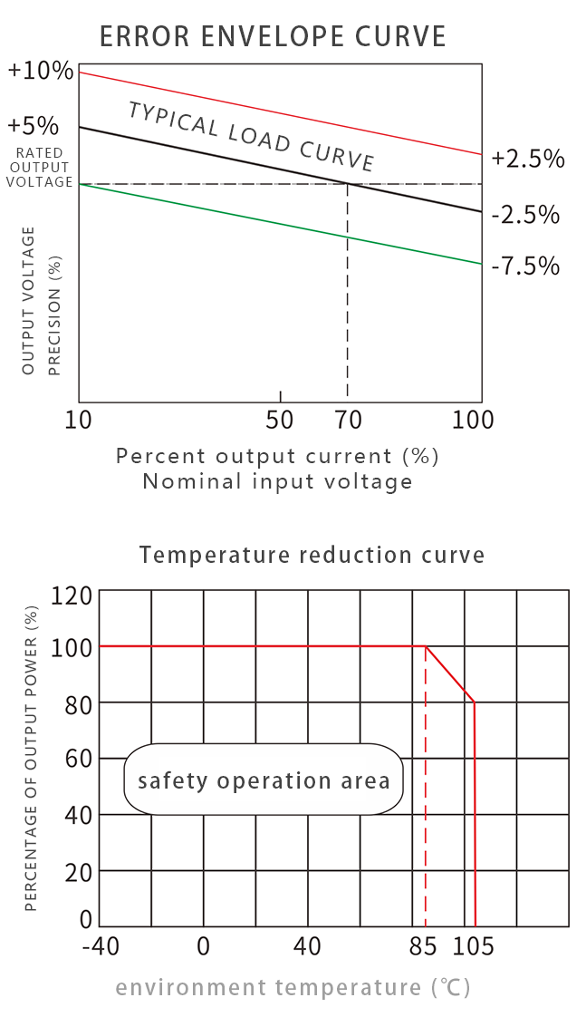
Product characteristic curve
PRODUCT CHARACTERISTICS CURVE
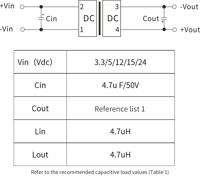
Typical application circuit
APPLICATION CIRCUIT
Recommended test circuit
If it is required to further reduce the input and output ripple, a capacitor filter network can be connected to the input and output ends. The application circuit is shown in the figure.
But care should be taken to select a suitable filter capacitor. If the capacitance is too large, it may cause startup problems. For each output, under the condition of ensuring safe and reliable operation, the recommended capacitive load value is shown in the attached table.
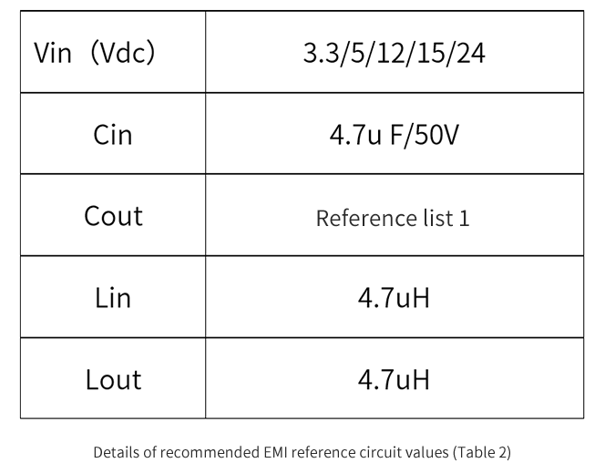
EMI typical application circuit
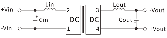
Recommended parameters:
Output load requirement
,
In order to ensure that the module can work efficiently and reliably, when in use, its minimum output load cannot be less than 10% of the rated load. If the power you need is really small, please connect a resistor in parallel between the positive and negative poles of the output (the sum of the actual power used by the resistors is greater than or equal to 10% of the rated power and the rated power of the selected resistor must be greater than 5 times the actual power used. , Otherwise the temperature of the resistor will be higher).
Ripple & noise test: twisted pair method 20MHz bandwidth
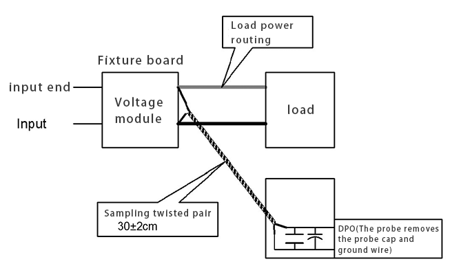
testing method:
1. Ripple noise is connected using 12# twisted pair, the oscilloscope bandwidth is set to 20MHz, 100M bandwidth probe, and 0.1uF polypropylene capacitor and 47uF high frequency low resistance electrolytic capacitor are connected in parallel to the probe end, and the oscilloscope sampling uses Sample sampling mode .
2. Connect the power input terminal to the input power supply, and the power output is connected to the electronic load through the fixture board. For testing, use a 30cm±2cm sampling line to sample directly from the power output port. The power line selects the corresponding wire diameter wire with insulation according to the output current. (As shown in FIG)


 Official mall
 Taobao shop
 TMALL
TMALL