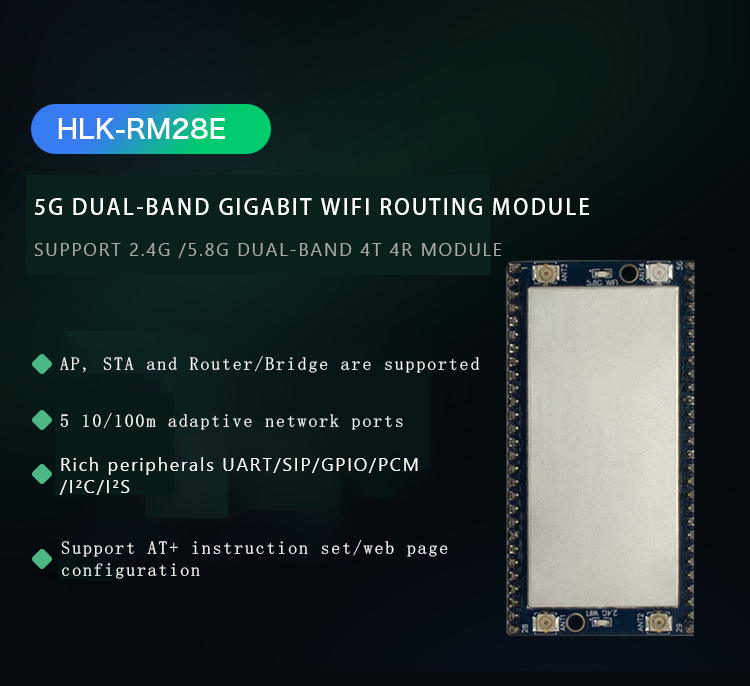
Product block diagram
Product Block diagram
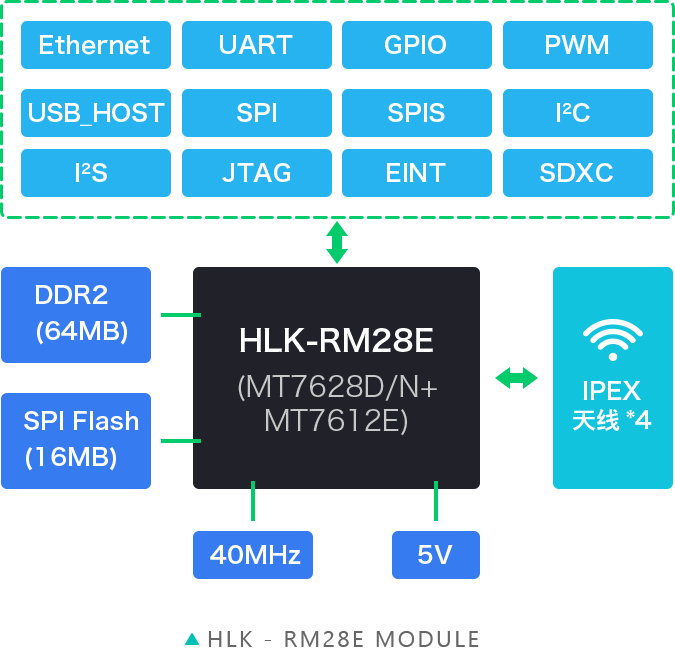
Interface and pin description
Interface&pin descriptions
Interface Description
|
|
|
| Interface Type | Module with interface | Factory firmware support interface |
| WiFi standard | IEEE802.11a/ac/b/g/n | stand by |
| Ethernet | 5 10M/100M adaptive | 1 WAN&4 LAN |
| UART | 2 way | All have transparent transmission function |
| SDIO | not support | not support |
| SPI | 1 way | not support |
| I2C | 1 way | not support |
| I2S | 1 way | not support |
| PWM | 2 way | not support |
| GPIO | 8 channels or more | Defined function |
Default pin function (serial port transparent transmission firmware)
|
|
|
|
|
| Serial number | name | Types of | Features | Description |
| 1 | GNP | P | Groud | System power |
| 2 | 5V | P | 5V input current ≥1000mA | System power |
| 3 | 5V | P | Same as above | System power |
| 4 | GND | P | Ground | System power |
| 5 | 3.3V | O | 3.3V output | - |
| 6 | GND | P | Ground | - |
| 7 | 5G_WLED | I/O | WiFi LED active low | Indicator light/can be suspended |
| 8 | SPI_CS0 | I/O | SPI bus chip select signal 0 | Undefined/please leave blank |
| 9 | SPI_MOSI | I/O | SPI bus data master out and slave in | Undefined/please leave open/cannot pull up or down |
| 10 | SPI_MISO | I/O | SPI bus data master in and slave out | Undefined/please leave open |
| 11 | SPI_CLK | I/O | SPI bus clock signal | Undefined/please leave open/cannot pull up or down |
| 12 | SPI_CS1 | I/O | SPI bus chip select signal 1 | Undefined/please leave open/cannot pull up or down |
| 13 | PERST_N | I/O | PCIe device reset output | Undefined/please leave open/cannot pull up or down |
| 14 | REF_CLK0 | I/O | Reference clock output | Undefined/please leave blank |
| 15 | WPS_RST | I | Enter AT mode pin | Undefined/please leave blank |
| 16 | PORST_N | I/O | CPU reset/active low | Reset output |
| 17 | LINK4 | I/O | PORT4 LED/active low | LAN4 network port light |
| 18 | LINK3 | I/O | PORT3 LED/active low | LAN3 network port light |
| 19 | LINK2 | I/O | PORT2 LED/active low | LAN2 network port light |
| 20 | LINK0 | I/O | PORT0 LED/active low | LAN1 network port light |
| twenty one | LINK0 | I/O | PORT0 LED/active low | WAN port light |
| twenty two | WLED_N | I/O | WiFi LED/active low | Signal indicator can be suspended |
| twenty three | UART_TXD1 | O | Serial 1 data transmission | Serial 1 output, please leave it open |
| twenty four | UART_RXD1 | I | Serial 1 data reception | Serial port 1 input, please leave it open |
| 25 | I2S_SDI | I/O | I2S data input terminal | Undefined/please leave blank |
| 26 | I2S_SDO | I/O | I2S data output terminal | Undefined/please leave open/cannot pull up or down |
| 27 | I2S_WS | I/O | I2S channel selection: 0 left/1 right | Undefined/please leave blank |
| 28 | I2S_CLK | I/O | I2S data bit clock | Undefined/please leave blank |
| 29 | I2C_SD | I/O | I2C bus data | Undefined/please leave blank |
| 30 | I2C_SCLK | I/O | I2C bus clock | Undefined/please leave blank |
| 31 | GPIO0 | I/O | Universal input output interface | Undefined/please leave blank |
| 32 | UART_RXD0 | I | Serial 0 data input | Serial port 0 input / please leave it unconnected |
| 33 | UART_TXD0 | O | Serial 0 data output | Serial port 0 output/don’t use please leave it open/can’t pull up or down |
| 34 | TXIP0 | I/O | PORT0 network signal receiving positive | WAN port, please leave it open |
| 35 | TXIN0 | I/O | PORT0 network signal receiving negative | Same as above |
| 36 | TXOP0 | I/O | PORT0 network signal sending positive | Same as above |
| 37 | TXON0 | I/O | PORT0 network signal transmission negative | Same as above |
| 38 | TXOP1 | I/O | PORT1 network signal sending positive | LAN1 port, please leave it open |
| 39 | TXON1 | I/O | PORT1 network signal transmission negative | Same as above |
| 40 | RXIP1 | I/O | PORT1 network signal receiving positive | Same as above |
| 41 | RXIN1 | I/O | PORT1 network signal reception negative | Same as above |
| 42 | RXIP2 | I/O | PORT2 network signal receiving positive | LAN2 port, please leave it open |
| 43 | RXIN2 | I/O | PORT2 network signal reception negative | Same as above |
| 44 | TXOP2 | I/O | PORT2 network signal sending positive | Same as above |
| 45 | TXON2 | I/O | PORT2 network signal transmission negative | Same as above |
| 46 | TXOP3 | I/O | PORT3 network signal sending positive | LAN3 port, please leave it open |
| 47 | TXON3 | I/O | PORT3 network signal transmission negative | Same as above |
| 48 | RXIP3 | I/O | PORT3 network signal reception is positive | Same as above |
| 49 | RXIN3 | I/O | PORT3 network signal reception negative | Same as above |
| 50 | RXIP4 | I/O | PORT4 network signal sending positive | LAN4 port, please leave it open |
| 51 | RXIN5 | I/O | PORT4 network signal transmission negative | Same as above |
| 52 | TXOP4 | I/O | PORT4 network signal receiving positive | Same as above |
| 53 | TXON4 | I/O | PORT4 network signal reception negative | Same as above |
| 54 | USB_DP | I/O | USB data positive | Undefined/please leave blank |
| 55 | USB_DM | I/O | USB data negative | Undefined/please leave blank |
| 56 | GND | P | Ground | Grounded |
Remarks:
1.I-input; O-output; I/O-digital I/O; P-power; IO port drive current 8mA;
2. The red on the name column refers to the chip startup, and cannot be pulled up or down from the outside or connected to the drive source;
3. The blue in the remarks column means that our factory default firmware has functions;
4. Except for the power pin pin2/3, the levels of other pins are all 3.3V.
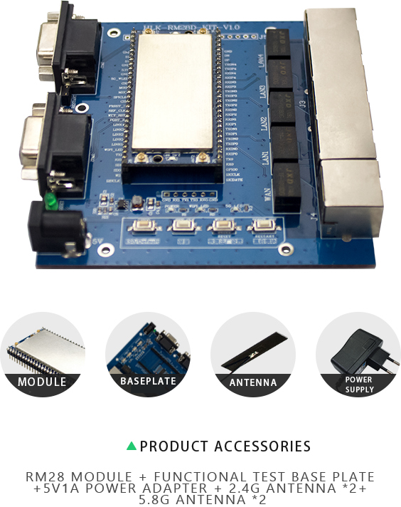
Product test suite
PRODUCT TEST KIT
Function Description
FUNCTION DESCRIPTION
Product functions can be divided into: default mode, serial port to Ethernet, serial port to WiFi CLIENT and serial port to WiFi AP.
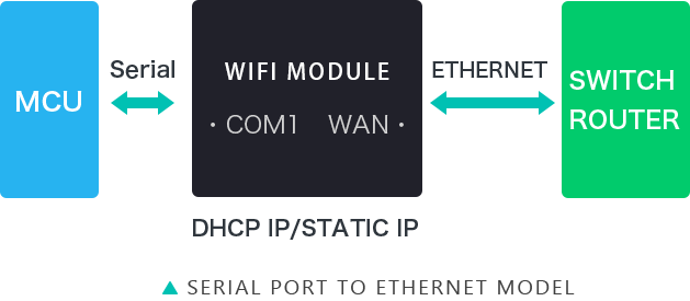
·In this mode, the WiFi and LAN functions are turned off, and the data of COM1 and the network data of WAN can be converted mutually through setting.
·The Ethernet can be configured as a dynamic IP address (DHCP) or as a static IP address (STATIC).
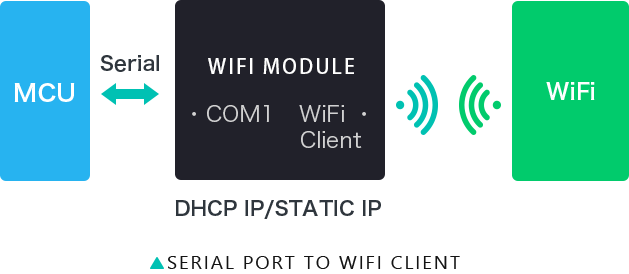
·In this mode, the WAN and LAN functions are turned off. Through settings, the data of COM1 and WiFi can be converted mutually.
·WiFi CLIENT can be configured as a dynamic IP address (DHCP) or a static IP address (STATIC).
·WiFi security supports all current encryption methods.
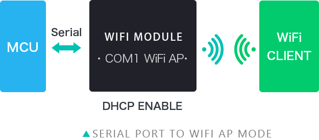
·In this mode (AP mode), the WAN and LAN functions are turned off, and the data of COM1 and WiFi can be converted mutually through setting.
·The WiFi device can connect to the product and become a device under the WiFi LAN.
·WiFi security supports all current encryption methods.
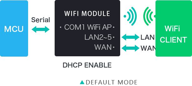
·In this mode (AP mode), WAN and LAN functions are available. Through settings, the data of COM1 and WiFi can be converted mutually.
·The WiFi device can connect to the product and become a device under the WiFi LAN. The WAN side defaults to dynamic IP address mode. LAN and WiFi are the same local area network, DHCP server is turned on by default
·WiFi security supports all current encryption methods.
The serial port/network data conversion of the product is divided into 4 modes: TCP Server, TCP Clinet, UDP Server, UDP Client.
TCP Server
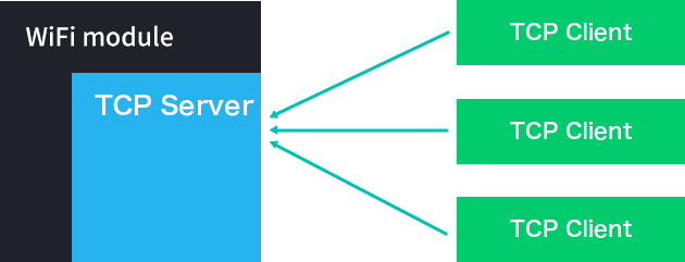
·In this mode, the module monitors the designated port and waits for the TCP Client to connect. After the connection, all TCP data is sent directly to the serial port, and the data from the serial port is sent to all TCP Clients.
TCP Client
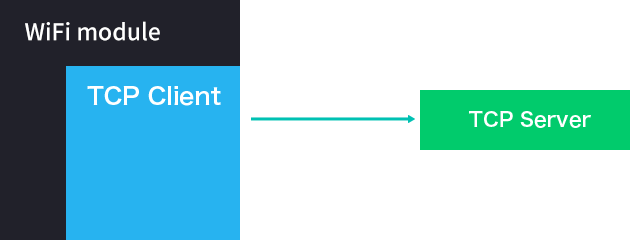
·In this mode, the module connects to the specified domain name/IP and port. All data sent from the TCP Server end is sent directly to the serial port, and the data from the serial port is sent to the TCP Server end. When the module acts as a TCP Server, it supports up to 2 TCP Clients to connect to the TCP Server.
·The abnormal network will cause the product to reconnect actively. When TCP active reconnection is available, TCP Server actively disconnects, and the product will actively reconnect immediately, otherwise the module will not reconnect
UDP Server
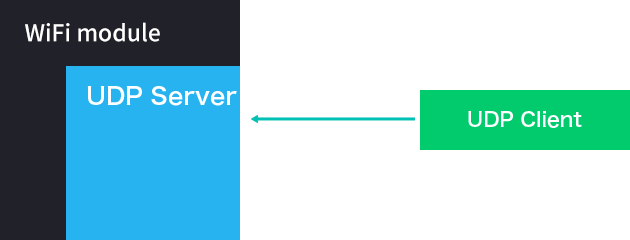
·In this mode, the module opens the local designated port. Once the data sent to this port is received, the module will send the data to the serial port and record the remote IP and port. The module will only record the remote information of the last connection. The data received by the serial port will be sent directly to the recorded remote IP and port.
UDP Client
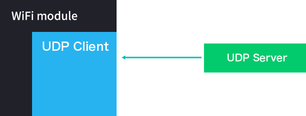
·In this mode, the module directly sends serial port data to the specified ip and port. The data returned from the server will be sent to the serial port.




 27/08/2020 14:51:25
 Official mall
 Taobao shop


