1W-A series power module selection
SELECTION OF POWER SUPPLY MODULE
5V(4.5-5.5V) constant voltage input 1W unregulated output
| MODEL | POWER | VOLTAGE | ELECTRICITY |
| HLK-1D0505A | 1W | 5V | 200mA |
| HLK-1D0512A | 1W | 12V | 83mA |
| HLK-1D0515A | 1W | 15V | 67mA |
| HLK-1D0524A | 1W | 24V | 42mA |
| *The same series of product size and pin packaging consistent |
| *The international standard pin size is 11.5x10x6mm |
product features
PRODUCT FEATURES
Ultra-miniature standard package SIP package and standard pins
Constant voltage input, isolated unregulated single output, 1W
Low super power consumption, standby power consumption is only 0.025W (input current 5mA)
Input and output isolation withstand voltage 1500VDC
Low ripple/noise <50mVp-p
High efficiency, conversion efficiency up to 88% (Typ)
Operating temperature range: -40°C~+85°C
Good output short circuit and over current protection and self-recovery
High reliability, long life design, continuous work>100000H
It is potted with high-quality environmentally friendly waterproof and thermal conductive glue, moisture-proof and vibration-proof, and meets the IP65 standard
Meet UL/CE/EMC and safety testing requirements
Can be used in medical, industrial control, electric power, instrumentation, communication, railway and other fields
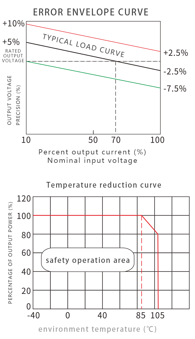
Product characteristic curve
PRODUCT CHARACTERISTICS CURVE
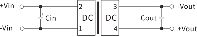
Typical application circuit
APPLICATION CIRCUIT
Recommended test circuit
If it is required to further reduce the input and output ripple, a capacitor filter network can be connected to the input and output ends. The application circuit is shown in the figure.
But care should be taken to select a suitable filter capacitor. If the capacitance is too large, it may cause startup problems. For each output, under the condition of ensuring safe and reliable operation, the recommended capacitive load value is shown in the attached table.
| Vin (Vdc) | 3.3/5/12/15/24 |
| Cin | 4.7u F/50V |
| Count | Refer to Table 1 |
| Lin | 4.7uH |
| Lout | 4.7uH |
Recommended capacitive load values are detailed (Table 1)
EMI typical application circuit
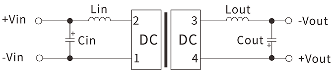
Recommended parameters:
| Vin (Vdc) | 5/12/15/24 |
| Cin | 4.7u F/50V |
| Count | Refer to Table 1 |
| Lin | 4.7uH |
| Lout | 4.7uH |
Recommended EMI reference circuit values are detailed (Table 2)
Output load requirement
In order to ensure that the module can work efficiently and reliably, when in use, its minimum output load cannot be less than 10% of the rated load. If the power you need is really small, please connect a resistor in parallel between the positive and negative poles of the output (the sum of the actual power used by the resistors is greater than or equal to 10% of the rated power and the rated power of the selected resistor must be greater than 5 times the actual power used. , Otherwise the temperature of the resistor will be higher).
Ripple & noise test: twisted pair method 20MHz bandwidth
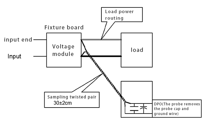
testing method:
1. Ripple noise is connected using 12# twisted pair, the oscilloscope bandwidth is set to 20MHz, 100M bandwidth probe, and 0.1uF polypropylene capacitor and 47uF high frequency low resistance electrolytic capacitor are connected in parallel to the probe end, and the oscilloscope sampling uses Sample sampling mode .
2. Connect the power input terminal to the input power supply, and connect the power output to the electronic load through the fixture board. Use a 30cm±2cm sampling line to sample directly from the power output port for testing. The power line selects the corresponding wire diameter wire with insulation according to the output current. (As shown in FIG)
Product application notes
PRODUCT APPLICATION NOTES
1. Input requirements: Ensure that the output voltage fluctuation range of the power supply does not exceed the input requirements of the DC/DC module itself, and the output power of the input power supply must be greater than the output power of the DC/DC module;
2. Recommended circuit 1: For occasions with general requirements for ripple and noise, a filter capacitor can be connected in parallel to the input and output ends. The external circuit is shown in the above figure (1). The recommended value of the filter capacitor is shown in Table (1) ). Output load requirements: Try to avoid no-load use. When the actual power consumption of the load is less than 10% of the module's output rated power or there is no-load phenomenon, it is recommended to connect a dummy load to the output end. The dummy load (resistance) can be in accordance with the rated power of the module. 5~10% calculation, resistance value=Uout/(1W*10%);
3. Overload protection: Under normal working conditions, the output circuit of this product has no protection against overload conditions. The easiest way is to connect a self-recovery fuse in series at the input end, or add a circuit breaker to the circuit;
4. The capacitance value of the external capacitor at the output end should not be too large, otherwise it will easily cause overcurrent or poor startup when the module starts;
5. If the product works below the minimum required load, it cannot be guaranteed that the product performance meets all the performance indicators in this manual;
6. The maximum capacitive load is tested under the input voltage range and full load conditions;
7. Except for special instructions, all indicators in this manual are measured at Ta=25℃/humidity <75%RH, nominal input voltage and output rated load;
8. All index test methods in this product manual are based on our company's standards;
9. Our company can provide product customization, and you can directly contact our technical staff for specific information;
10. Product specifications are subject to change without notice.
Dimensions
DIMENSIONS
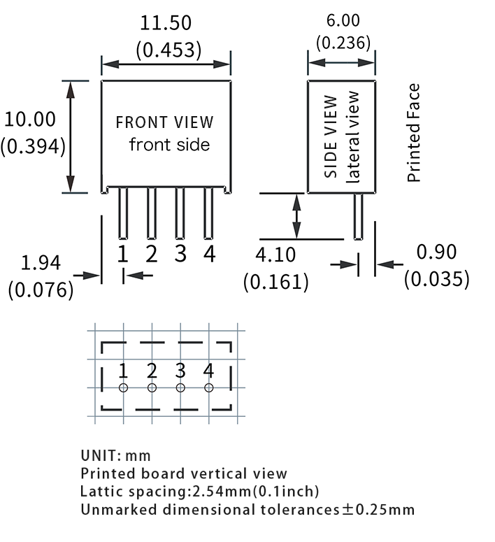
Pin description:
1: GND; 2: +Vin; 3: -Vo 4: +Vo ;
*Note: If the definition of each pin of the power module does not match the selection manual, the label on the physical label shall prevail.


 Official mall
 Taobao shop
 TMALL
TMALL