product features
PRODUCT FEATURES
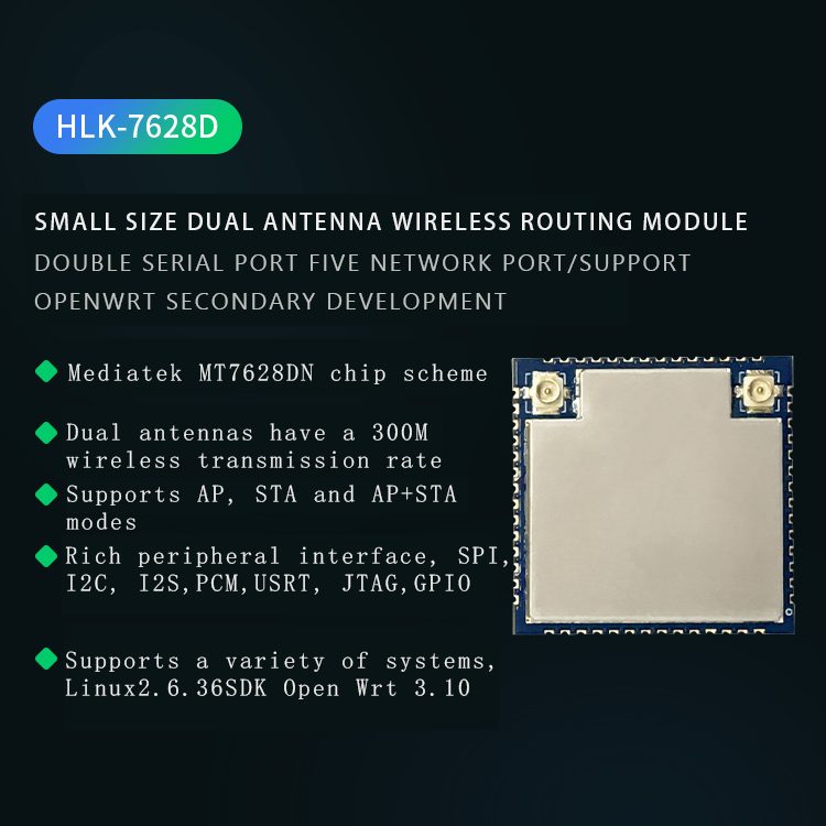
Super data processing capability, MCU frequency up to 580MHz
Dual antenna 300M wireless transmission rate
Support 802.11b/g/n/v mode
20/40 channel bandwidth
Support AP, STA and AP+STA mixed mode
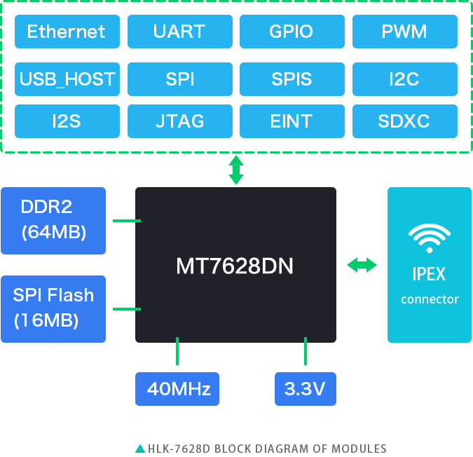
5 10/100M adaptive network ports, 1 USB2.0 host interface, multiple interfaces SPI/SD-XC/eMMC
Rich peripheral interfaces, SPI, I2C, I2S, PCM, UART, JTAG, GPIO
Support multiple encryption methods WEP64/128, TKIP, AES, WPA, WPA2, WAPI
Support QoS, WMM, WMM-PS
Support Linux2.6.36 SDK, OpenWrt3.10
Product Structure
PRODUCT STRUCTURE

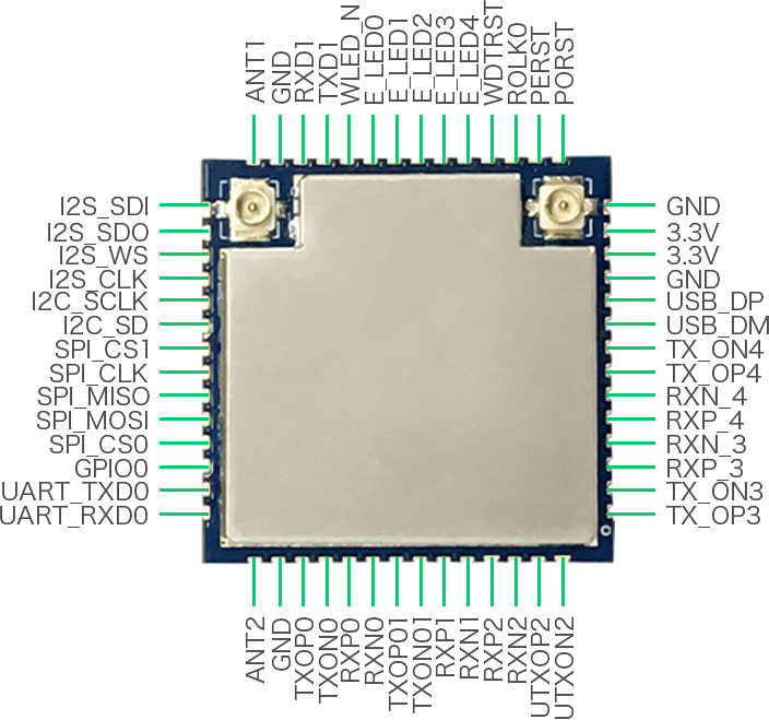
Pin definition
PIN DEFINITION

Pin description
| Serial number | Network name | Description |
| 1 | PORST_N | Module reset (restart), active low |
| 2 | PERST_N | PCle device reset output |
| 3 | REF_CFKO | Reference clock output |
| 4 | WDT_RST_N | Watchdog timeout reset |
| 5 | EPHY_LED4 | PORT4 LED, active low |
| 6 | EPHY_LED3 | PORT3 LED, active low |
| 7 | EPHY_LED2 | PORT2 LED, active low |
| 8 | EPHY_LED1 | PORT1 LED, active low |
| 9 | EPHY_LED0 | PORT0 LED, active low |
| 10 | WLED_N | WiFi LED, active low |
| 11 | UART_TXD1 | Serial 1 data transmission |
| 12 | UART_TXD1 | Serial 1 data receiving |
| 13 | GND | Ground |
| 14 | ANT | RF interface, the pin of the external antenna is not connected by default |
| 15 | I2S_SDI | I2S data input terminal |
| 16 | WDT_RST_N |
I2S data input terminal |
|
17 |
I2S_WS |
I2S channel selection, 0: left; 1: right |
|
18 |
I2S_CLK |
I2S data bit clock |
|
19 |
I2C_SCLK |
I2C bus clock |
|
20 |
I2C_SD |
SPI bus chip select signal 1 |
|
twenty one |
SPI_CS1 |
SPI bus chip select signal 1 |
|
twenty two |
SPI_CLK |
SPI bus clock signal |
|
twenty three |
SPI_MISO |
SPI bus data master in and slave out |
|
twenty four |
SPI_MOSI |
SPI bus data master out and slave in |
|
25 |
SPI_CS0 |
SPI bus chip select signal 0 |
|
26 |
GPIO0 |
Universal input output interface |
|
27 |
UART_TXD0 |
modify |
|
28 |
UART_TXD0 |
Serial 0 data output |
|
29 |
ANT1 |
RF interface, the pin of the external antenna is not connected by default |
|
30 |
GND |
Ground |
|
31 |
MDI_RP_P0 |
PORT0 network signal receiving positive |
|
32 |
MDI_RN_P0 |
PORT0 network signal receiving negative |
|
33 |
MDI_TP_P0 |
PORT0 network signal sending positive |
|
34 |
MDI_TN_P0 |
PORT0 network signal transmission negative |
|
35 |
MDI_TP_P1 |
PORT1 network signal sending positive |
|
36 |
MDI_TN_P1 |
PORT1 network signal transmission negative |
|
37 |
MDI_RP_P1 |
PORT1 network signal reception is positive |
|
38 |
MDI_RN_P1 |
PORT1 network signal reception negative |
|
39 |
MDI_RP_P2 |
PORT2 network signal reception is positive |
|
40 |
MDI_RN_P2 |
PORT2 network signal reception negative |
|
41 |
MDI_TP_P2 |
PORT2 network signal sending positive |
|
42 |
MDI_TN_P2 |
PORT2 network signal transmission negative |
|
43 |
MDI_TP_P3 |
PORT3 network signal sending positive |
|
44 |
MDI_TN_P3 |
PORT3 network signal transmission negative |
|
45 |
MDI_RP_P3 |
PORT3 network signal reception is positive |
|
46 |
MDI_RN_P3 |
PORT3 network signal reception negative |
|
47 |
MDI_RP_P4 |
PORT4 network signal receiving positive |
|
48 |
MDI_RN_P4 |
PORT4 network signal reception negative |
|
49 |
MDI_TP_P4 |
PORT4 network signal sending positive |
|
50 |
MDI_TN_P4 |
Watchdog timeout reset |
|
51 |
USB_DP |
USB data positive |
|
52 |
USB_DM |
USB data negative |
|
53 |
GND |
Ground |
|
54 |
3.3VD |
3.3V input, power supply current ≥800mA |
|
55 |
3.3VD |
3.3V input, power supply current ≥800mA |
|
56 |
GND |
Ground |
Remarks:
1. I-input; O-output; I/O-digital I/O; P-power; RF-radio frequency interface. IO port drive current is 10mA.
2. The red on the name bar means: it is related to the startup of the chip, and it cannot be pulled up or down from the outside, and it cannot be connected to the drive source.
3. The blue on the remarks column means: our factory default firmware has this function.
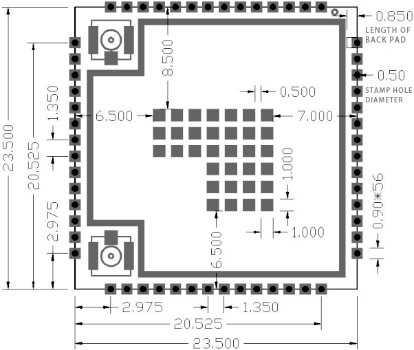
Module size chart
MODULE SIZE

Description:
1. The middle pad is a thermal pad and can be grounded;
2. The module pins are symmetrical structure;
3. The size of the pad on the picture is the actual size, please enlarge it appropriately when making the package


 27/08/2020 14:49:48
 Official mall
 Taobao shop


